Electronics Workout
to understand deeply the working of electronic circuits
Saturday, 5 March 2022
Thursday, 1 October 2015
What is the phase of Voltage and Current in AC signal
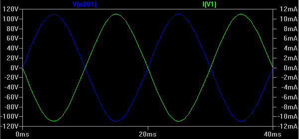
I always perceived that the Voltage and Current are in same phase in a AC voltage source, and using LTSpice probing for Voltage at V1 source and and another probe measuring current through V1 shows a plot as shown below that indicates indeed there is a 180 degree phase difference.
But actually in real world there is no phase difference between Voltage and Current in the Voltage Source. The above plot is because of the way LTSpice probes the Current through the Voltage Source (V1).
If you notice the probe at the (V1) is pointed downwards and the probe at the R1 load resistor is also pointed downwards. That means the current is measured in the reverse direction in the voltage source (V1) so the actual plot shown is -I (V1). This is the reason we get 180 degree phase shift in LTSpice Simulator for Current measured through Voltage Source.
The below is the plot of current measured across the R1 load resistor.
Current in Half Wave Rectifier
In this circuit a AC voltage source of 110V 50Hz sine wave is supplied to the diode and the diode rectifies the signal to DC.
If we probe across Load R1 for Voltage, we would get half-wave and the -ve cycle of the voltage is clipped out by the diode.
Negative cycle of the Current through the load is also clipped by the diode.
Subscribe to:
Comments (Atom)


